|
 |
WITH IN-BUILT POSITION SENSING AND LOAD MONITORING
DESCRIPTION:
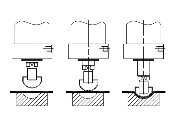
For the first time in India we are introducing a pneumo hydraulic cylinder with in - built load and position monitoring sensor. This unit is an integrated pneumo hydraulic cylinder together with reservoir, the pneumatic cylinder gives rapid approach of the piston rod towards work. The hydraulic cylinder acts an intensifier raising the hydraulic pressure on the piston to generate a large force and the piston rod will have a stroke of max 32mm under hydraulic pressure at any point of stroke of air cylinder. The intensification point is manually selected and pressurized by a solenoid direction control valve. These pneumatic cylinders have many important features, these are mentioned below.
Quicloc also specializes in the Manufacturing of high quality Pneumatic Cylinder Seal Kits for Hydraulic Cylinders in Bangalore.
FEATURES:
- Output force can be varied
- High cycle rates for increased Production
- Hydraulic power packs not required
- Compact device
- Built-in LVDT for stroke sensing
- Seal life up to 10 Million cycles
- Application: General & Special Purpose
- Pneumatic forces: 1-4 tons
- Total stroke: upto 200mm
- Power stroke: upto 32mm
- Operating pressure: upto 10bar
NOTE:
- This configuration of pneumo hydraulic power cylinder should always
be mounted vertically with the front flange mounting.
- Ordering specification for seal kit. Add prefix “SK” to the model
number. Only specialist/service personnel can change the seal.
- Max. force during power stroke only.
SPECIFICATION :
Type : PNEUMO HYDRAULIC POWER CYLINDER
Total Stroke —Approach Stroke +Power Stroke
Medium: Hydraulic Oil (Servo System 32) And Filtered Lubricated Air
* Specifications subject to improvements
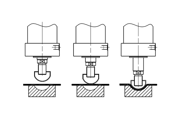
TYPICAL EXAMPLE OF APPLICATION:
All dimensions in mm.
| SL No., |
Model No |
A |
L |
S |
| 01 |
P13020—50/6 |
464 |
512 |
1 |
| 02 |
P13020—100/6 |
564 |
682 |
71 |
| 03 |
P13020—150/6 |
664 |
842 |
131 |
| 04 |
P13020-50/12 |
501 |
548 |
-36 |
| 05 |
P13020-100/1k |
607 |
702 |
54 |
| 06 |
P13020-150/1 |
701 |
842 |
94 |
| 07 |
P13020—75/24 |
626 |
673 |
-111 |
| 08 |
P13020—100/24 |
676 |
723 |
-51 |
| 09 |
P13020-150/24 |
776 |
842 |
19 |
SPECIFICATION CHART :
All dimensions in mm.
| SL No., |
Model No |
A |
L |
S |
| 01 |
P13021—50/6 |
563 |
662 |
43 |
| 02 |
P13021—100/6 |
613 |
787 |
118 |
| 03 |
P13027—150/6 |
713 |
987 |
218 |
| 04 |
P13027—200/6 |
813 |
1187 |
318 |
| 05 |
P13027—50/i2 |
564 |
520 |
-8 |
| 06 |
P13027—100/I. |
664 |
787 |
67 |
| 07 |
P13027—150/i. |
764 |
987 |
167 |
| 08 |
P1i021-2C0/f |
864 |
1187 |
267 |
| 09 |
P13027-100/24 |
758 |
814 |
-27 |
| 10 |
P13021—150/24 |
858 |
988 |
74 |
| 11 |
P13027 -200/24 |
970 |
1188 |
162 |
| SL No., |
Model No |
A |
L |
S |
| 01 |
P13022—50/6 |
546 |
610 |
5 |
| 02 |
P13022—100/6 |
646 |
790 |
85 |
| 03 |
P13022—150/6 |
746 |
970 |
165 |
| 04 |
P13022—200/6 |
864 |
1770 |
265 |
| 05 |
P130P2—50/12 |
590 |
650 |
-40 |
| 06 |
P13022—100/I4 |
690 |
790 |
41 |
| 07 |
P13022—150/i4 |
790 |
970 |
121 |
| 08 |
P13022—200/I4 |
890 |
1170 |
221 |
| 09 |
P13022—75/24 |
724 |
783 |
-84 |
| 10 |
P13022—l00/2 |
774 |
833 |
-44 |
| 11 |
P13022—150/24 |
874 |
970 |
37 |
| 12 |
P13022—200/24 |
974 |
1170 |
137 |
| SL No., |
Model No |
A |
L |
S |
| 01 |
P13023—50/6 |
571 |
635 |
5 |
| 02 |
P13023—100/6 |
671 |
815 |
85 |
| 03 |
P13023—150/6 |
771 |
995 |
165 |
| 04 |
P13023—200/6 |
889 |
1195 |
265 |
| 05 |
P130P2—50/12 |
615 |
675 |
-40 |
| 06 |
P13023—100/I4 |
715 |
815 |
41 |
| 07 |
P13023—150/i4 |
815 |
995 |
121 |
| 08 |
P13023—200/I4 |
995 |
1195 |
221 |
| 09 |
P13023—75/24 |
749 |
808 |
-84 |
| 10 |
P13023—l00/2 |
799 |
858 |
-44 |
| 11 |
P13023—150/24 |
899 |
995 |
37 |
| 12 |
P13023—200/24 |
999 |
1195 |
137 |
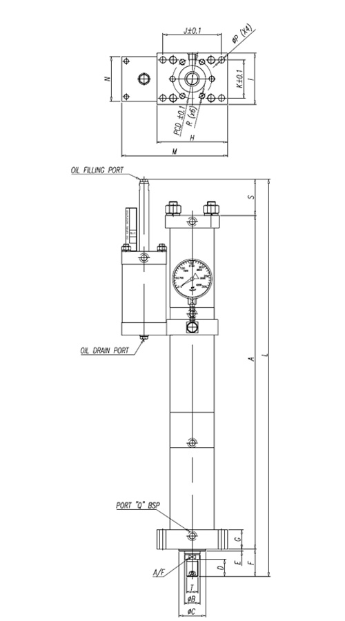
| SLNO. |
MODEL NO. |
T |
B |
C |
D |
E |
F |
G |
H |
I |
J |
K |
M |
N |
P |
Q |
R |
PCD |
A/F |
| 03 |
P13022 |
M36X2P |
50 |
75 |
35 |
5 |
59.5 |
40 |
195 |
146 |
165 |
108 |
295 |
142 |
17 |
|
M16 |
105 |
46 |
| 02 |
P13021 |
M24X2P |
32 |
55 |
35 |
4 |
56 |
40 |
145 |
105 |
120 |
78 |
205 |
92 |
13 |
|
- |
- |
27 |
| 01 |
P13020 |
M20X2P |
25 |
45 |
28 |
4 |
47 |
30 |
110 |
76 |
88 |
55 |
155 |
74 |
10.5 |
|
- |
- |
19 |
*Specifications subject to improvements.
|
|
|
|
- Compact and Self contained
design allows for ease of
installation.
DESCRIPTION:
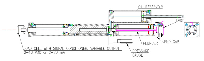
The power cylinder designed and manufactured by Quicloc is combination of hydraulic cylinder and an oil reservoir. The oil reservoir plays a key role of increasing the force. The pneumatic present in the cylinder amplifies the oil pressure, hence enabling the pneumo hydraulic cylinder to work with an additional boost of force. The intensification point is manually selected and pressurized by a solenoid direction control valve.
FEATURES:
- Output force con be varied.
- High cycle rates for increased Production
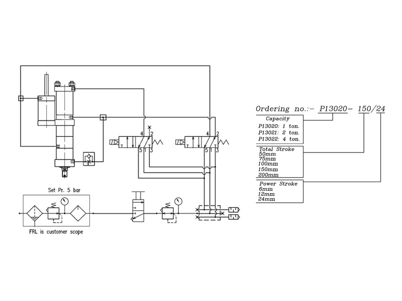
- Min / Max Operating Pneumatic Pressure 3/5 bar
- Hydraulic power Packs not required
- Compact device
NOTE:
-
This configuration of pneumo hydraulic power cylinder should
always be mounted vertically with the front flange mounting.
- Refer recommendations in page R1 before selection & use.
- Ordering specification for seal kit. Add prefix "SK" to the model number.
- Only specialist/service personnel can change the seal.
- Max. Force during Power Stroke Only.
- Oil should be replaced
every 500 working hours
to ensure long life.
- Change filters when
changing Oil or 4 times a
year whichever comes
first.
- Output flow rates should
be matched to hydraulic
Components used in the
system.
SPECIFICATION CHART
All dimensions in mm.
| Model/Stroke |
P13020 |
P13021 |
P13022 |
| Approach |
1.07 |
1.28 |
3.62 |
| Power |
9.7 |
19.5 |
43.6 |
| Return |
1.31 |
2.11 |
5.15 |
| P31104 |
6.8 |
100 |
1.5 |
| Model/Stroke |
Air Pressure in bar |
| 3 |
4 |
5 |
| P13020 |
4.5 |
6.5 |
9.7 |
| P13021 |
11.5 |
15.5 |
19.5 |
| P13022 |
26.1 |
34.9 |
43.6 |
Specifications subject to improvements.
| SL No., |
Model No |
A |
L |
S |
| 01 |
P13020—50/6 |
464 |
512 |
1 |
| 02 |
P13020—100/6 |
564 |
682 |
71 |
| 03 |
P13020—150/6 |
664 |
842 |
131 |
| 04 |
P13020-50/12 |
501 |
548 |
-36 |
| 05 |
P13020-100/1k |
607 |
702 |
54 |
| 06 |
P13020-150/1 |
701 |
842 |
94 |
| 07 |
P13020—75/24 |
626 |
673 |
117 |
| 08 |
P13020—100/24 |
676 |
723 |
-51 |
| 09 |
P73020-150/24 |
776 |
842 |
19 |
SPECIFICATION CHART :
All dimensions in mm.
| SL No., |
Model No |
A |
L |
S |
| 01 |
P73021—50/6 |
563 |
662 |
43 |
| 02 |
P13021—100/6 |
613 |
787 |
118 |
| 03 |
P13027—150/6 |
713 |
987 |
278 |
| 04 |
P13027—200/6 |
813 |
1187 |
318 |
| 05 |
P13027—50/i2 |
564 |
520 |
-8 |
| 06 |
P13027—100/I. |
664 |
787 |
67 |
| 07 |
P13027—150/i. |
764 |
987 |
167 |
| 08 |
P1i021-2C0/f |
864 |
1187 |
267 |
| 09 |
P13027-100/24 |
758 |
814 |
-27 |
| 10 |
P13021—150/24 |
858 |
988 |
74 |
| 11 |
P73027 -200/24 |
970 |
1188 |
162 |
| SL No., |
Model No |
A |
L |
S |
| 01 |
P73022—50/6 |
546 |
610 |
5 |
| 02 |
P13022—700/6 |
646 |
790 |
85 |
| 03 |
P13022—150/6 |
746 |
970 |
765 |
| 04 |
P13022—200/6 |
864 |
1770 |
265 |
| 05 |
P130P2—50/12 |
590 |
650 |
-40 |
| 06 |
P13022-100/I4 |
690 |
790 |
41 |
| 07 |
P13022—150/i4 |
790 |
970 |
121 |
| 08 |
P13022-200/I4 |
890 |
1770 |
221 |
| 09 |
P 73022—75/24 |
724 |
783 |
-84 |
| 10 |
P73022-l00/2 |
774 |
833 |
-44 |
| 11 |
P13022-750/24 |
874 |
970 |
37 |
| 12 |
P13022—200/24 |
974 |
1770 |
137 |
All dimensions in mm.
| SLNO. |
MODEL NO. |
T |
B |
C |
D |
E |
F |
G |
H |
I |
J |
K |
M |
N |
P |
Q |
R |
PCD |
A/F |
| 03 |
P13022 |
M36X2P |
50 |
75 |
35 |
5 |
59.5 |
40 |
195 |
146 |
165 |
108 |
295 |
142 |
17 |
|
M16 |
105 |
46 |
| 02 |
P13021 |
M24X2P |
32 |
55 |
35 |
4 |
56 |
40 |
145 |
105 |
120 |
78 |
205 |
92 |
13 |
|
- |
- |
27 |
| 01 |
P13020 |
M20X2P |
25 |
45 |
28 |
4 |
47 |
30 |
110 |
76 |
88 |
55 |
155 |
74 |
10.5 |
|
- |
- |
19 |
Specifications subject to improvements.
Click here to download a pdf:
Hydro_Pneumatic_Power_Cylinder
|
|