|
|
DESCRIPTION:
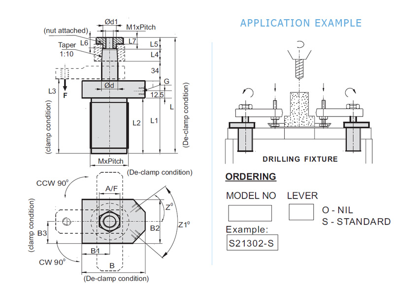
These Hydraulic Clamping elements are pull type swing cylinders,
wherein a part of the total stroke is used to swing the arm (stroke to swing).
The shorter part is available as clamping stroke. These swing clamps are
having a special feature during the rotation (swing), it covers 20mm
stroke and thereafter it travels vertically for 10mm clamping stroke. The
total stroke is 30mm.
FEATURES:
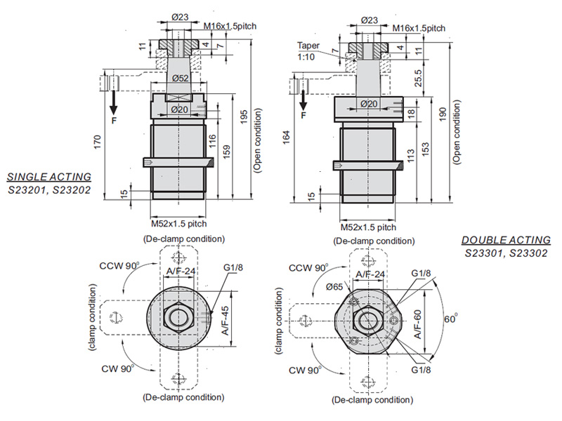
- Min./ Max. Operating Pressure 10/250 bar.
- Large clamping range.
- Total stroke 30 mm. Swing stroke 20 mm. Vertical stroke 10 mm.
- Arm swing will be 90 2 .
- 360 adjustable arm location.
NOTE :
- Refer general design notes before selection &use.
- CW Model dimensions are same asCCWmodel dimensions.
- Refer accessories sheet page No. X1 & X2 for Clamp arm and ring
nut details.
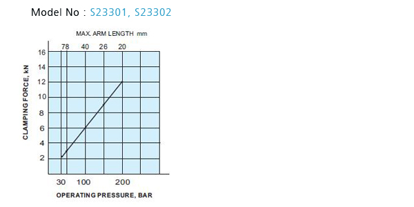
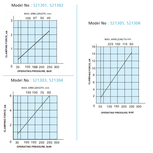
- Given forces are for the standard arm lever. Pressure and flow
should be reduced if clamp arm length is increased (Refer graph
sheet G1).
- Models with overload protection are available as special.
Dimensions are different. Contact : Quicloc.
- Ordering specification for seal kit. Add prefix "SK" to the model
Number.
|
- Actual clamping takes place when the Cylinder has
completed its 90 swing stroke.
- only
Clamping allowed only in clamping stroke not in swing
stroke.
- Do not exceed max. flow rate. If flow rates are exceeded,
swing cylinder indexing mechanism may be permanently
damaged.
- If the system flow rate
exceeds, use one way flow
control valve in the upstream
hydraulic lines.
- Length of Clamping arm,
weight of Clamping arm,
max. Permissible flow rate
and working pressure are all
important. Refer graphs for
arm length and working
pressure.
- Keep weight of Clamping
arm to a minimum.
|
|
GRAPH :
 |
DESCRIPTION:
These Hydraulic Clamping elements are pull type cylinder, wherein a part
of the total stroke is used to swing the piston (stroke to swing). The
shorter part is available as clamping stroke. These swing clamps are
having a special feature during the rotation (swing, it covers 20mm
stroke and thereafter travels vertically for 10mm clamping stroke. The
total stroke is 30mm.
FEATURES:
- Min./ Max. Operating Pressure 10/250 bar.
- Large Clamping range.
- Total stroke 30 mm. Swing stroke 20 mm. Vertical stroke 10 mm.
- Arm swing will be 90 2
- 360 adjustable arm location.
NOTE :
- Refer general design notes before selection &use.
- CW Model dimensions are same asCCWmodel dimensions.
- Refer accessories sheet page No. X1 & X2 for Clamp arm and ring
nut details.
- Given forces are for the standard arm lever. Pressure and flow
should be reduced if clamp arm length is increased (Refer Graph
sheet No. G1).
- Models with overload protection are available as special.
- Dimensions are different. Contact Quicloc.
- Ordering specification for seal kit. Add prefix "SK" to the model
Number.