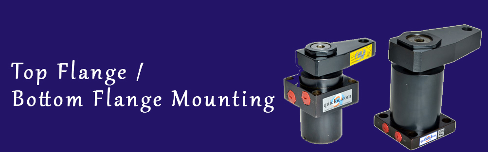
Bottom or Top Flange Mounted Swing Clamps |
 |
DESCRIPTION:
Swing clamps can be chosen in two different mounting configurations namely bottom flange mounted swing clamp or top flange mounted swing clamp. The selection depends on the space available and the clamping points available in the design of your machine. These Hydraulic Clamping elements are pull type swing cylinders, wherein a part of the total stroke is used to swing the arm (stroke to swing). The shorter part is available as clamping stroke. These swing clamps are having a special feature during the rotation (swing), it covers 20mm stroke and thereafter it travels vertically for 10mm clamping stroke. The total stroke is 30mm.
In case of need for further customization or discussion regarding the top and bottom flange mounting please contact us. We would be happy to help your find the right swing clamp configuration for you.
FEATURES:
- Min./Max. Operating Pressure 10/250 bar.
- Large clamping range.
- Total stroke 30 mm. Swing stroke 20 mm. Vertical stroke 10 mm.
- Arm swing will be 90 2
- 360 adjustable arm location.
NOTE :
- Refer general design notes before selection &use.
- CWModel dimensions are same asCCWmodel dimensions.
- Refer accessories sheet page No. X2 for clamp arm details.
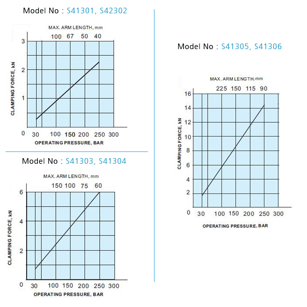
- Given forces are for the standard arm lever. Pressure and flow
should be reduced if clamp arm length is increased (Refer Graph
sheet No. G1).
- Ordering specification for seal kit. Add prefix "SK" to the model
Number.
- Actual clamping takes place when the
Cylinder has completed its 90 swing stroke.
- Only
Clamping allowed only in clamping stroke not in
swing stroke.
- Do not exceed max. flow rate. If flow rates are
exceeded, swing cylinder indexing mechanism
may be permanently damaged.
- If the system flow rate
exceeds, use one way
flow control valve in the
upstream hydraulic lines.
- Length of Clamping arm,
weight of Clamping arm,
max. Permissible flow
rate and working pressure
are all important. Refer
graphs for arm length and
working pressure.
- Keep weight of Clamping
arm to a minimum.
GRAPH :
 |
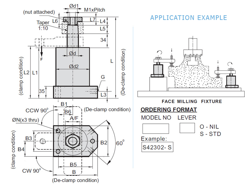
SPECIFICATION CHART
All dimensions in mm.
| Model No. : CW |
S41301 |
S41303 |
S41305 |
| CCW |
S41302 |
S41304 |
S41306 |
| Force F kN @ 100 bar |
1 |
2.6 |
6.3 |
| @ 200 bar |
1.9 |
5.3 |
12.6 |
| Piston dia /RodØd |
25 / 20 |
40 / 32 |
63 / 50 |
| Stroke: Swing stroke |
20 |
20 |
20 |
| Vertical stoke |
10 |
10 |
10 |
| Oil Volume cc |
5.3 |
13.5 |
34.6 |
| M1 x Pitch |
M16x1.5 |
M24x1.5 |
M33x2 |
| Ød1 |
22 |
33 |
52 |
| Ød2 |
48 |
65 |
90 |
| L + 0.5 |
174 |
200 |
225 |
| L1 |
112 |
132 |
145 |
| L2 |
87 |
107 |
120 |
| L3 |
116 |
136 |
149 |
| L4 |
16 |
20 |
26 |
| L5 |
12 |
14 |
20 |
| L6 |
10 |
12 |
18 |
| L7 |
7 |
8 |
10 |
| B |
68 |
90 |
127 |
| B1 |
30.5 |
39 |
54 |
| B2 |
58 |
78 |
108 |
| B3 |
42 |
60 |
82 |
| B4 |
29 |
39 |
54 |
| B5 |
53 |
73 |
101 |
| B6 |
22.5 |
30 |
41 |
| G |
1/8" |
1/4" |
1/4" |
| A/F |
26 |
42 |
60 |
| ØM x deep |
14.5x10 |
19x14 |
26x18 |
| ØN |
9 |
14 |
18 |
| Max. flow rate lpm |
0.15 |
0.6 |
1.6 |
| Std. clamp arm |
XS2501 |
XS4001 |
XS6301 |
Specifications subject to improvements.
Click here to download a pdf:
S41301-02 | S41303-04 | S41305-06
DESCRIPTION:
These Hydraulic Clamping elements are pull type cylinder, wherein a part
of the total stroke is used to swing the piston (stroke to swing). The shorter
part is available as clamping stroke. These swing clamps are having a
special feature during the rotation (swing), it covers 20mm stroke and
thereafter travels vertically for 10mm clamping stroke. The total stroke is
30mm.
FEATURES:
- Min./ Max. Operating Pressure 10/250 bar.
- Large clamping range.
- Total stroke 30 mm. Swing stroke 20 mm. Vertical stroke 10 mm
- Arm swing will be 90 2.
- 360 adjustable arm location.
NOTE :
- Refer general design notes before selection & use.
- CW Model dimensions are same as CCW model dimensions./
- Refer accessories sheet page No. X2 for clamp arm details.
- Given forces are for the standard arm lever. Pressure & flow
should be reduced if clamp arm length is increased (Refer Graph
sheet No. G1).
- Models with overload protection are available as special.
- Dimensions are different. Contact Quicloc.
- Ordering specification for seal kit. Add prefix "SK" to the model
Number.
- Actual clamping takes place when the
Cylinder has completed its 90 swing stroke.
- only
Clamping allowed only in clamping stroke not in
swing stroke.
- Do not exceed max. flow rate. If flow rates are
exceeded, swing cylinder indexing mechanism
may be permanently damaged.
- If the system flow rate
exceeds, use one way
flow control valve in the
upstream hydraulic lines.
- Length of Clamping arm,
weight of Clamping arm,
max. Permissible flow
rate and working pressure
are all important. Refer
graphs for arm length and
working pressure.
- Keep weight of Clamping
arm to a minimum.
GRAPH :
 |
SPECIFICATION CHART
All dimensions in mm.
| Model No. : CW |
S42301 |
S42303 |
S42305 |
| CCW |
S42302 |
S42304 |
S42306 |
| Force F kN @ 100 bar |
1 |
2.6 |
6.3 |
| @ 200 bar |
1.9 |
5.3 |
12.6 |
| Piston dia /RodØd |
25 / 20 |
40 / 32 |
63 / 50 |
| Stroke: Swing stroke |
20 |
20 |
20 |
| Vertical stoke |
10 |
10 |
10 |
| Oil Volume cc |
5.3 |
13.5 |
34.6 |
| M1 x Pitch |
M16x1.5 |
M24x1.5 |
M33x2 |
| Ød1 |
22 |
33 |
52 |
| Ød2 |
48 |
65 |
90 |
| L ± 0.5 |
174 |
200 |
225 |
| L1 |
112 |
132 |
145 |
| L2 |
116 |
136 |
149 |
| L3 |
20 |
22 |
22 |
| L4 |
12 |
14 |
20 |
| L5 |
16 |
20 |
26 |
| L6 |
10 |
12 |
18 |
| L7 |
7 |
8 |
10 |
| B |
68 |
90 |
127 |
| B1 |
30.5 |
39 |
54 |
| B2 |
58 |
78 |
108 |
| B3 |
42 |
60 |
82 |
| B4 |
29 |
39 |
54 |
| B5 |
53 |
73 |
101 |
| B6 |
22.5 |
30 |
41 |
| G |
1/8" |
1/4" |
1/4" |
| A/F |
26 |
42 |
60 |
| ØN |
9 |
14 |
18 |
| Max. flow rate lpm |
0.15 |
0.6 |
1.6 |
| Std. clamp arm |
XS2501 |
XS4001 |
XS6301 |
Specifications subject to improvements.
Click here to download a pdf:
S42301-02 | S42303-04 | S42305-06
DESCRIPTION:
These Hydraulic Clamping elements are pull type swing cylinders, wherein a part of the total stroke is used to swing the arm (stroke to swing). The shorter part is available as clamping stroke. These swing clamps are having a special feature during the rotation (Swing), it covers 10 mm stroke and thereafter it travels vertically for 14 mm clamping stroke. The total stroke is 24 mm.
FEATURES:
- Min/Max. operating pressure 20/1 80 bar.
- Large clamping range.
- Double acting ranges.
- Very compact cylinder design.
- 360 adjustable arm location.
- Arm swing will be 90c± 0.2°
- Total stroke 24mm. Swing Stroke 10 mm.
- Clamp stroke 14 mm
NOTE :
- Refer general design notes before selection & use.
- Given forces are for the standard arm lever.
- Pressure and flow should be reduced if clamp arm length is increased (Refer catalog graph sheet No.-G1) Ordering specification for seal kit.
- Add prefix SK" to the model Number.
- If the system flow rate exceeds, use one way flow control valve in the upstream hydraulic lines.
- Length of Clamping arm, weight of Clamping arm, max. Permissible flow rate and working pressure are all important.
- Refer graphs for arm length and working pressure.
- Keep weight of clamping arm to a minimum.
- Actual clamping takes place only when the Cylinder has completed its 900 swing stroke.
- Clamping allowed only in clamping stroke not in swing stroke.
- Do not exceed max. flow rate. If flow rates are exceeded, swing cylinder indexing mechanism may be permanently damaged.
GRAPH :
 |
| Part No |
a |
c |
b |
g |
h |
d1 |
d |
M |
e |
d |
| XS4003 |
115 |
75 |
26 |
23 |
18 |
34 |
31.8 |
M16 |
23 |
52 |
| XS5003 |
144 |
100 |
30 |
34 |
28 |
45.5 |
39.8 |
M16 |
26 |
60 |
| XS6303 |
178 |
120 |
40 |
34 |
28 |
56 |
49.8 |
M20 |
40 |
78 |
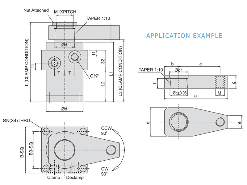
SPECIFICATION CHART
All dimensions in mm.
| Model No. : CW |
S43301 |
S43303 |
S43305 |
| CCW |
S43302 |
S43304 |
S43306 |
| Force F kN @ 100 bar |
7KN |
10KN |
17KN |
| Piston dia /RodØd |
40 / 20 |
50/40 |
63/50 |
| Oil Vol.clamp |
11cc |
18cc |
28cc |
| Oil Vol.clamp |
30cc |
48cc |
75cc |
| Swing stroke/Clamp stroke |
10/14 |
10/14 |
10/14 |
| M1 x Pitch |
M28x1.5P |
M36x1.5P |
M46x2P |
| Ød1 |
32 |
40 |
50 |
| Ød2 |
60 |
75 |
90 |
| L |
129 |
160 |
160 |
| L1 |
97 |
116 |
116 |
| L2 |
52 |
67 |
67 |
| L3 |
101 |
120 |
120 |
| T |
16.5 |
15.5 |
18 |
| B-SQ |
75 |
85 |
105 |
| B3-SQ |
60 |
65 |
80 |
| ØN |
11 |
11 |
17 |
| Max. flow rate lpm |
0.6 |
1 |
1.6 |
Specifications subject to improvements.
Click here to download a pdf:
S43301-02 | S43303-04 | S43305-06
- If the system flow rate exceeds, use one way flow control
valve in the upstream hydraulic lines.
- Length of Clamping arm, weight of Clamping arm, Max.
Permissible flow rate and working pressure are all
important. Refer graphs for arm length and working
pressure.
- Keep weight of Clamping arm to a minimum.
DESCRIPTION:
These Hydraulic Clamping elements are pull type swing
cylinders, wherein a part of the total stroke is used to swing
the arm (stroke to swing). The shorter part is available as
clamping stroke. These swing clamps are having a special
feature during the rotation (swing), it covers 10 mm stroke
and thereafter it travels vetically for 14 mm clamping stroke.
The total stroke is 24 mm.
FEATURES:
- Min/Max. Operating Pressure 20/180 bar.
- Large clamping range
- Double acting ranges
- Very compact cylinder design
- 360 adjustable arm location
- Arm swing will be 90 + 0.2
- Total stroke 24mm. Swing stroke 10 mm. Clamp stroke
14 mm
NOTE :
- Refer general design notes before selection & use.
- Given forces are for the standard arm lever. Pressure
and flow should be reduced if clamp arm length is
increased (Refer catalog graph sheet No.-G)
- Ordering specification for seal kit. Add prefix "SK" to
the model Number.
- Actual clamping
takes place
when the Cylinder
has completed its 90
swing stroke.
- Only
Clamping allowed
only in clamping
stroke not in swing
stroke.
- Do not exceed max.
flow rate. If flow rates
are exceeded, swing
cylinder indexing
mechanism may be
p e r m a n e n t l y
damaged.
GRAPH :
 |
| Part No |
a |
c |
b |
g |
h |
d1 |
d |
M |
e |
d |
| XS4003 |
115 |
75 |
26 |
23 |
18 |
34 |
31.8 |
M16 |
23 |
52 |
| XS5003 |
144 |
100 |
30 |
34 |
28 |
45.5 |
39.8 |
M16 |
26 |
60 |
| XS6303 |
178 |
120 |
40 |
34 |
28 |
56 |
49.8 |
M20 |
40 |
78 |
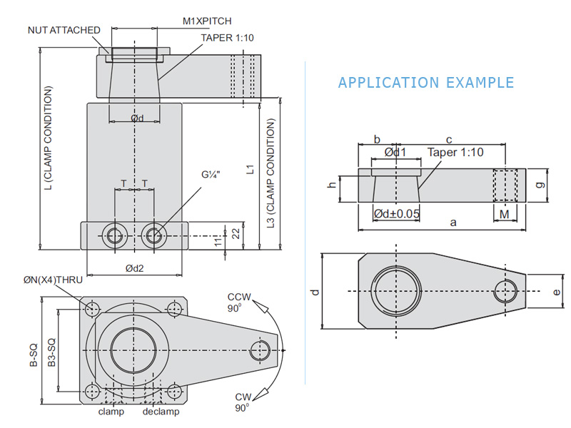
SPECIFICATION CHART
All dimensions in mm.
| Model No. : CW |
S44301 |
S44303 |
S44305 |
| CCW |
S44302 |
S44304 |
S44306 |
| Force F kN @ 100 bar |
7KN |
10KN |
17KN |
| Piston dia /RodØd |
40 / 32 |
50/40 |
63/50 |
| Oil Vol.clamp |
11cc |
18cc |
28cc |
| Oil Vol.clamp |
30cc |
48cc |
75cc |
| Swing stroke/Clamp stroke |
10/14 |
10/14 |
10/14 |
| M1 x Pitch |
M28x1.5P |
M36x1.5P |
M46x2P |
| Ød1 |
32 |
40 |
50 |
| Ød2 |
60 |
75 |
90 |
| L |
129 |
160 |
160 |
| L1 |
97 |
116 |
116 |
| L2 |
52 |
67 |
67 |
| L3 |
101 |
120 |
120 |
| T |
16.5 |
15.5 |
18 |
| B-SQ |
75 |
85 |
105 |
| B3-SQ |
60 |
65 |
80 |
| ØN |
11 |
11 |
17 |
| Max. flow rate lpm |
0.6 |
1 |
1.6 |
Specifications subject to improvements.
Click here to download a pdf:
S44301-02 | S44303-04 | S44305-06
|
|