|
 |
- Actual clamping takes place only when
the Cylinder has completed its 90 swing
stroke.
- Clamping allowed only in clamping
stroke not in swing stroke.
- Do not exceed max. flow rate. If flow
rates are exceeded, swing cylinder
indexing mechanism may be
permanently damaged.
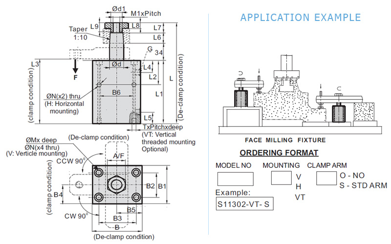
DESCRIPTION:
The Block type design enables quick cylinder assembly and
disassembly through horizontal and vertical mounting holes. Special
threads are provided for vertical mounting operation. These double
acting swing clamps are having special feature during rotation
(swing) it covers 20mmstroke and there after it travels vertically for
10mm clamping stroke.
FEATURES:
- Forces given are axial forces. To obtain force at ‘F’ refer Graph
Sheet Page No. G1.
- Min. / Max. Operating Pressure 10/250 bar.
- Large clamping range.
- Block type body design with symmetrical mounting hole layout.
- Total stroke 30 mm. Swing stroke 20 mm.Vertical stroke 10mm.
- Arm swing will be 90 ±2 .(Special swing angles given optionally)
- 360 adjustable arm location.
NOTE :
- Refer general design notes before selection &use.
- CWModel dimensions are same asCCWmodel dimensions.
- Refer accessories sheet Page No. X2 for Clamp arm details.
- Given forces are for the standard arm lever. Pressure and flow
should be reduced if clamp arm length is increased (Refer Graph
Sheet Page No. G1).
- Ordering specification for seal kit. Add prefix "SK" to the model
Number.
|
- If the system flow rate
exceeds, use one way
flow control valve in the
upstream hydraulic lines.
- Length of Clamping arm,
weight of Clamping arm,
max. Permissible flow
rate and working pressure
are all important. Refer
graphs for arm length and
working pressure.
- Keep weight of Clamping
arm to a minimum.
|
|
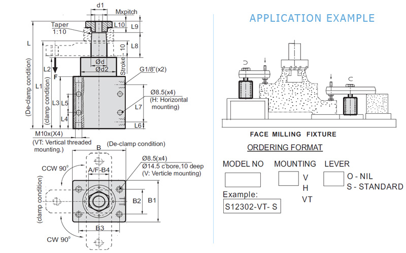
DESCRIPTION:
The Block type design enables for quick cylinder assembly and disassembly
by means of horizontal and vertical mounting holes. These double acting swing
clamps are having special feature during rotation (swing) it covers an internal
stroke and swings horizontally for 90 stroke and there after travels vertically
for10mmclamping stroke.
FEATURES:
- Min./ Max. Operating Pressure 30/100 bar.
- Large clamping range.
- Double acting ranges.
- Block type body design with symmetrical mounting hole layout.
- 360 adjustable arm location.
- Arm swing will be 90 2
- Zero vertical stroke during 90 horizontal swing.
NOTE :
- Refer general design notes before selection &use.
- CWModel dimensions are same asCCmodel dimensions.
- For ClampArm details refer accessories sheet page No. X2.
- Given forces are for the standard arm lever. Pressure & flow should be
reduced if clamp arm length is increased (Refer graph sheet page No.
G1).
- Clamping Stroke is 10mm.
- Ordering specification for seal kit.Add prefix "SK" to the model Number.